
- Low outgas cable
- Heat-resistance
- Oil resistance
- Flame retardant
- Flexing
- Noise resistance
- Weather-ability(UV resistant)
Low outgas cable
-
APPLICATION
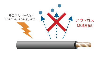
This low outgas cable is possible to use wiring in a clean room such as the semiconductor manufacturing, because a cable do not volatilize of contaminant such as the DOP, DBP and siloxane.
-
CHARACTERISTICS
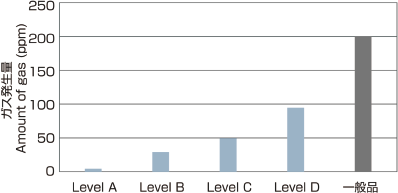
The amount of the out gas generation has been decreased to 1/10 more than past PVC cables. Moreover, we developed ecology low outgas cable which does not use PVC such as olefin materials.
Outgas level
| A | B | C | D | |
|---|---|---|---|---|
| Volatilizing of plasticizer | few | many | ||
| Products |
Low outgas cable (ECOLEX-Series) (05Z1-K) (07Z1-K) |
H05V-K+RV MTW+H05V-K MTW+H07V-K |
RO-FLEX 1100T(S) RO-FLEX 7700T(S) RO-FLEX 22710T |
RO-FLEX 10T RO-FLEX 50T RO-FLEX 80T |
Analysis of outgas
Dynamic Headspace-Gas Chromatography-Mass Spectrometry(DHS-GC-MS)
Thermal Desorption Cold Trap(TCT)
Heating conditions 80°C×60min
The contaminant does not volatilize.
Phosphate esters
Siloxane
 Back to top
Heat resistance
Heat resistance level
| A | B | C | D | ||
|---|---|---|---|---|---|
| Conductor temperature |
Rated temperature EN, IEC |
90°C | 90°C | 70°C | 70°C |
| Test requirement EN, IEC | 135°C×336h | 80°C×168h | |||
| Insulation temperature | Rated temperature UL, CSA | 105°C | 80°C | 80°C | 60°C |
| Test requirement UL, CSA | 136°C×168h | 113°C×168h | 100°C×168h | ||
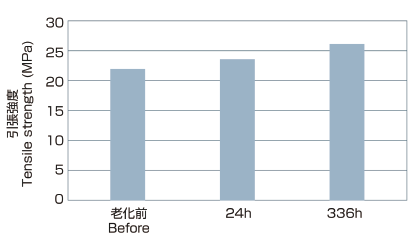
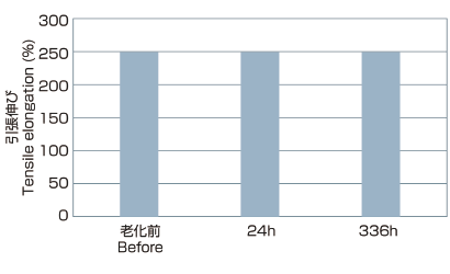
Test result (135°C×336h) ex.MTW+H07V-K
- IECInternational Electrotechnical Commission
- ENEuropean Norm
- ULUnderwriters Laboratories
- CSACanadian Standard Association
- ※This data is measurements and the reference.
Back to top
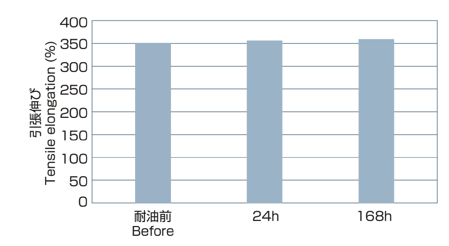
Oil resistance
Oil resistance level
| A | B | C | D | |
|---|---|---|---|---|
| EN, IEC | 90°C×168h | ー | 90°C×24h | ー |
| UL, CSA | ー | 100°C× 96h 60°C×168h |
ー | ー |
| JIS | ー | ー | ー | 70°C×4h |
Test result (90°C×24h, 168h) ex.RO-FLEX 1100T
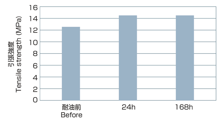 Test Oil ASTM IRM902
 Test Oil ASTM IRM902
- IECInternational Electrotechnical Commission
- ENEuropean Norm
- ULUnderwriters Laboratories
- CSACanadian Standard Association
- ※This data is measurements and the reference.
Back to top
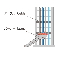
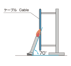
Flame retardant
Flame reatrdant level
| Standard | A | B | C | D |
|---|---|---|---|---|
| IEC | IEC 60332-3 Category A |
IEC 60332-3 Category C |
EN 50265-2-1 (IEC 60332-1) |
IEC 60332-2 Horizontal flame test |
| UL | ー | VW-1 for CT use | VW-1 | Horizontal flame test |
| CSA | ー | FT4 | FT1 | FT2 |
| JIS, JCS, PSE | ー | JIS C 3521 JCS 7397 |
PSE flame retardant test | JIS C 3005 |
| Level A | Test outline | Apparatus | ||||||||||||||
|---|---|---|---|---|---|---|---|---|---|---|---|---|---|---|---|---|
|
IEC 60332-3 Category A |
|
|
| Level B | Test outline | Apparatus | ||||||||||||||
|---|---|---|---|---|---|---|---|---|---|---|---|---|---|---|---|---|
|
VW-1 for CT use |
|
|
||||||||||||||
| CSA FT4 |
|
|||||||||||||||
|
IEC 60332-3 Category C |
|
|||||||||||||||
|
JIS C 3521 JCS 7397 |
Flame test method for flame retardant sheath of communication cables.
|
| Level C | Test outline | Apparatus | ||||||||
|---|---|---|---|---|---|---|---|---|---|---|
| VW-1 |
|
|
||||||||
| FT1 |
|
|||||||||
|
EN 50265-2-1 (IEC 60332-1) |
|
|
| Level D | Test outline | Apparatus | ||||||
|---|---|---|---|---|---|---|---|---|
| JIS C 3005 |
Test methods for rubber or plastic insulated wires and cables.
|
|
- IECInternational Electrotechnical Commission
- ULUnderwriters Laboratories
- JISJapan Industrial Standard
- CSACanadian Standard Association
- JSCJapanese Cable Makers' Association Standard
- PSEDenan Law
Back to top
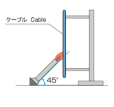
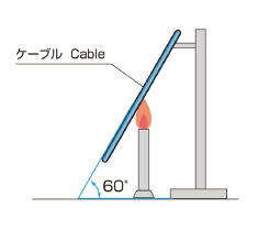
Flexing
Flexing level
| Condition | A | B | C | D |
|---|---|---|---|---|
| C Type | ≧10,000,000/cycle | ≧5,000,000/cycle | ≧3,000,000/cycle | <3,000,000/cycle |
| U Type | ≧10,000,000/cycle | ≧3,000,000/cycle | ≧1,000,000/cycle | <1,000,000/cycle |
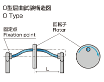
| O Type | ≧5,000,000/cycle | ≧3,000,000/cycle | ≧1,000,000/cycle | <1,000,000/cycle |
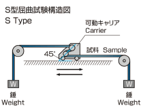
| S Type | ≧5,000,000/cycle | ≧1,000,000/cycle | ≧500,000/cycle | <500,000/cycle |
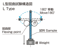
| L Type | ≧2,000,000/cycle | ≧500,000/cycle | ≧300,000/cycle | <300,000/cycle |
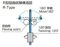
| R Type | ≧1,000,000/cycle | ≧300,000/cycle | ≧100,000/cycle | <100,000/cycle |
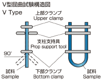
| V Type | ≧300,000/cycle | ≧100,000/cycle | ≧20,000/cycle | <20,000/cycle |
- ※This data is reference value.
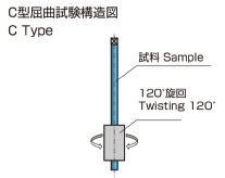
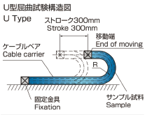
| Type | Test outline | Apparatus |
|---|---|---|
|
C Type (Torsion test) |
|
|
|
U Type (Cable bearing test) |
|
|
|
O Type (Bending test) |
|
|
|
S Type (Moving bending test) |
|
|
| L Type (90℃ Loopback test) |
|
|
|
R Type (Robot test) |
|
|
|
V Type (Seismic test) |
|
|
Back to top
Noise resistance
Noise resistance level
| Contents | A | B | C | D |
|---|---|---|---|---|
| Braid shield | ○ | ○ | --- | --- |
| Twisted pair | ○ | --- | ○ | --- |
-
About noise
There are many causes of noise, including electrostatic induction and electromagnetic induction.
-
About electrostatic induction
An electrostatic shield blocks electrostatic induction (copper shields, etc.). Copper shields are cheap, easy to process, and highly versatile. However, they only have an effect on electrostatic induction and do not have an effect on electromagnetic induction.
-
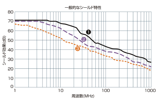
Shield type
-
 Braided shield:Great for controlling noise in low-level frequencies
-
 Spiral shield:Flexibility,Highly bendable
-
 Aluminum polyester shield:100% consistency with a small amount
-
-
About electromagnetic induction
A magnetic shield blocks electromagnetic induction.
A twisted wire is often used as a measure against noise from electromagnetic induction.
With this, noise can be reduced by about 80 – 90%, as even if electromagnetic induction occurs, the effects of the noise are cancelled out by each wire. -
About electrostatic induction
EMC(Electoro Magnetic Compatibility) refers to electromagnetic compatibility, and is a regulation regarding electromagnetic noise interference and resistance given off by electrical equipment.
EMI(Electoro Magnetic Interference):Regulatory EMS(Electoro Magnetic Specification) related to the effects of electrical equipment itself:Regulations established to control the occurrence of noise given off from other equipment are collectively known as EMC. These regulations generally regulate all electronic equipment, including cables. This is because, even if the same cable is used, the overall shield effect may change as a result of the combination of electronic equipment or operating frequencies. EN 50525-2-51 Transfer Impedance is provided as a cable shield feature requirement, and our shielded cables conform to the 250mΩ/m or lower: 30MHz transfer impedance required value and are valid EMC measures(2014/30/EU) based on the EMC directive.
Back to top
Weather(UV)resistance
Weather resistance level
| Contents | A | B | C | D |
|---|---|---|---|---|
| Color | Black color is recommended for weather resistance cable. | |||
| Cable type | Cable type color Black | Single wire color Black |
Cable type other than color Black |
Single wire other than color Black |
| Change rate(%) | < -20 % | < -30 % | < -40 % | < -50 % |
Xenon weatherometer test
| Item | Contents |
|---|---|
| Light source | 7kW Xenon-arc lamp |
| Test time | 720hours |
| Spray cycle | Dry interval between spraying 102min ± 0.5min |
| Duration of spraying 18min ± 0.5min | |
| Relative spectral irradiancee | 550W/㎡(290~880nm) |
| Black-panel temperature | 65±3°C |
| Relative humidity | 50±5% |
Back to top